Getting Started
Skateboarding carries inherent risks. By using our products, you acknowledge and accept these risks, including the potential for serious injury or death.
ATTENTION BATCH 1 CUSTOMERS
- Check your board’s axles for improper assembly.
- Check for stuck axle nuts and replace if necessary.
- Contact us if you need any assistance.
BEFORE CHANGING IDLER POSITION
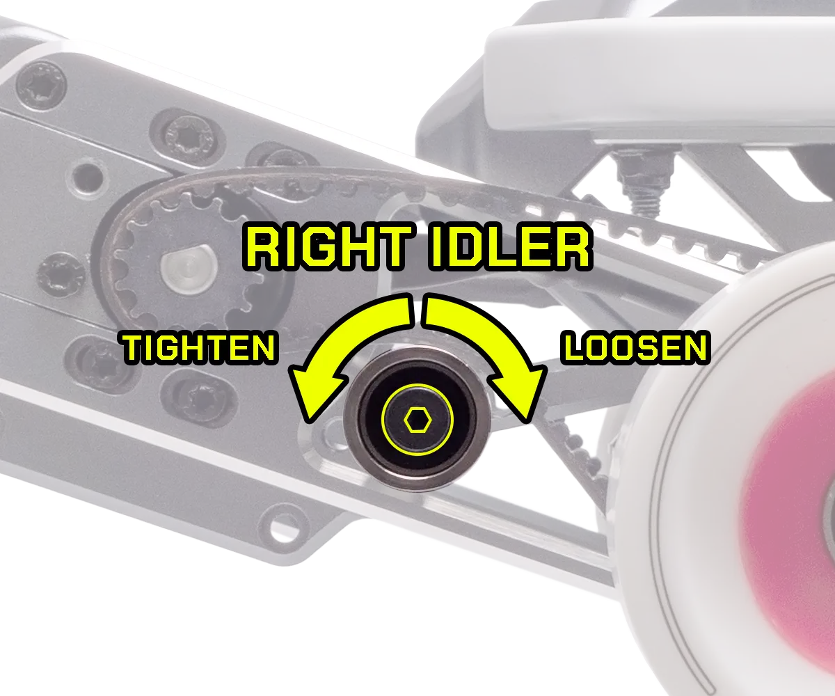
Note that the bolt securing the right-side idler pulley has reverse threads. Turn it clockwise to loosen, counterclockwise to tighten.
Safety First
- Always wear a helmet and appropriate safety gear.
- Practice in a safe environment free of traffic and obstacles.
- Learn how to brake with your foot.
- Learn how to fall safely.
- Ride within your capabilities.
- Ride on well-paved surfaces only.
- Ride in well-lit conditions only.
- Keep a safe distance from pedestrians and other vehicles.
- Slow down to walking speed around pedestrians.
- Obey local traffic laws.
- Do not let water get inside the board.
- Do not ride in wet, icy, or other slippery conditions.
- Do not ride under the influence of alcohol or other substances.
- Do not ride downhill with a fully charged battery. [Why?]
- Do not ride while distracted.
- Do not open the board without instructions from Parsec Support.
Product Overview
Board
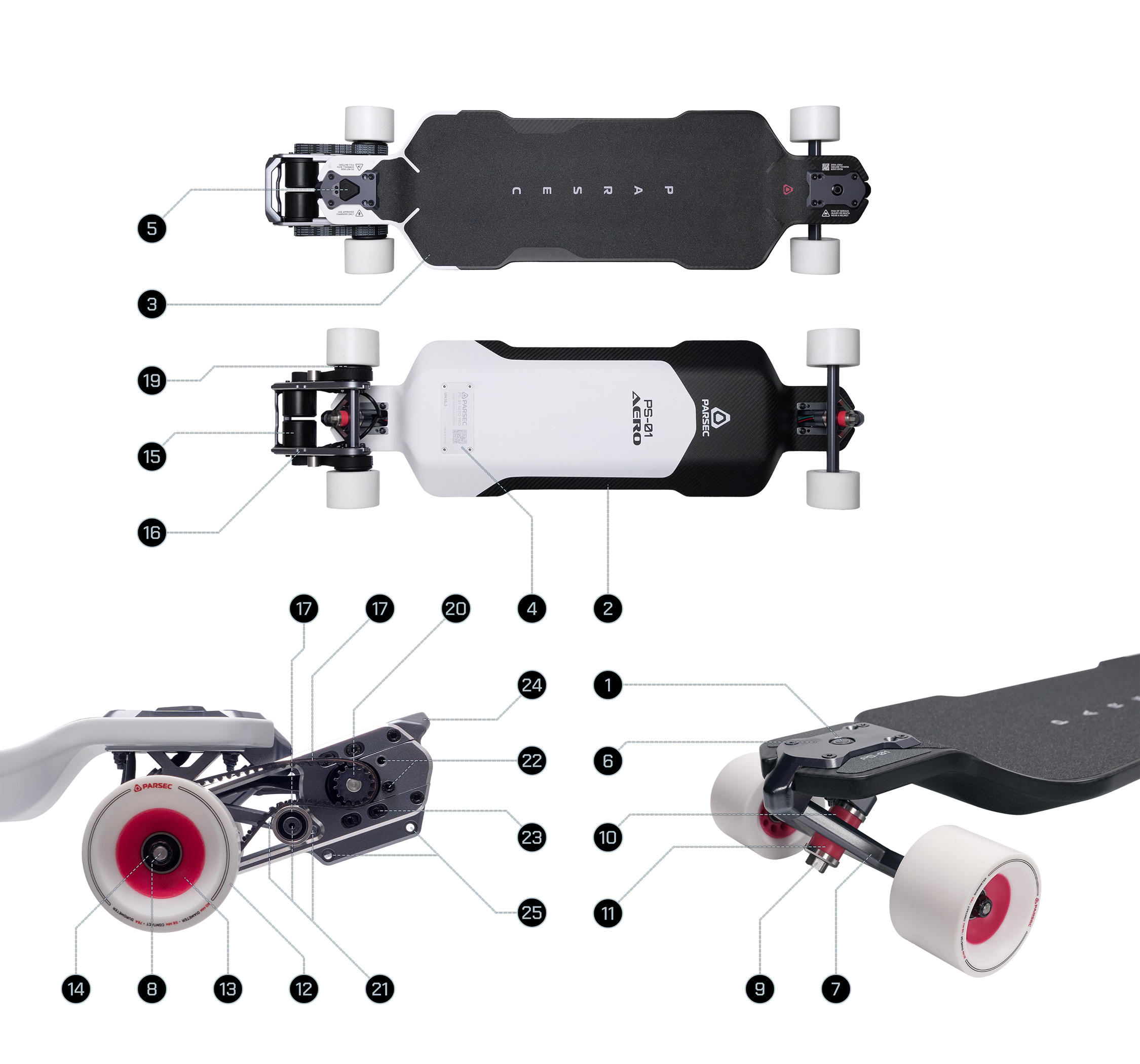
- Power Button
- Monocoque Deck
- Griptape
- ESC Heatsink
- Charge Port and Cover
- Truck Baseplate
- Truck Hanger
- Truck Axle
- Kingpin
- Bushing (Board Side)
- Bushing (Road Side)
- Wheel Thane
- Wheel Core
- Wheel Bearing
- Motor
- Motor Mount
- Belt
- Drive Gear
- Driven Gear / Wheel Pulley
- Idler Pulley
- Idler Position Presets
- Motor Position Presets
- Tension Adjustment Slots
- Picktail
- Motor Guard Mounting Points
Remote Controller
Note: Early batches of Aero Pros ship with a full-featured provisional remote. This user manual provides instructions for that remote and will be updated when the Parsec remote ships.
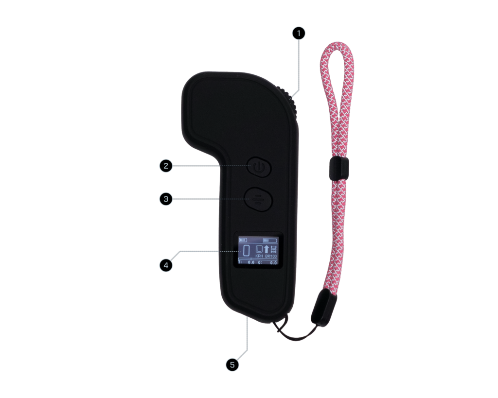
- Throttle Wheel
- Power Button
- Mode Button
- Display
- Charge Port
Remote Display
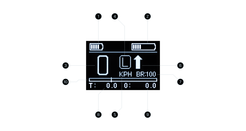
- Remote Battery
- Board Battery
- Current Speed
- Current Ride Mode
- Unit of Measure
- Direction
- Max Brake Level
- Trip Meter
- Odometer
- Power Gauge
In the Box
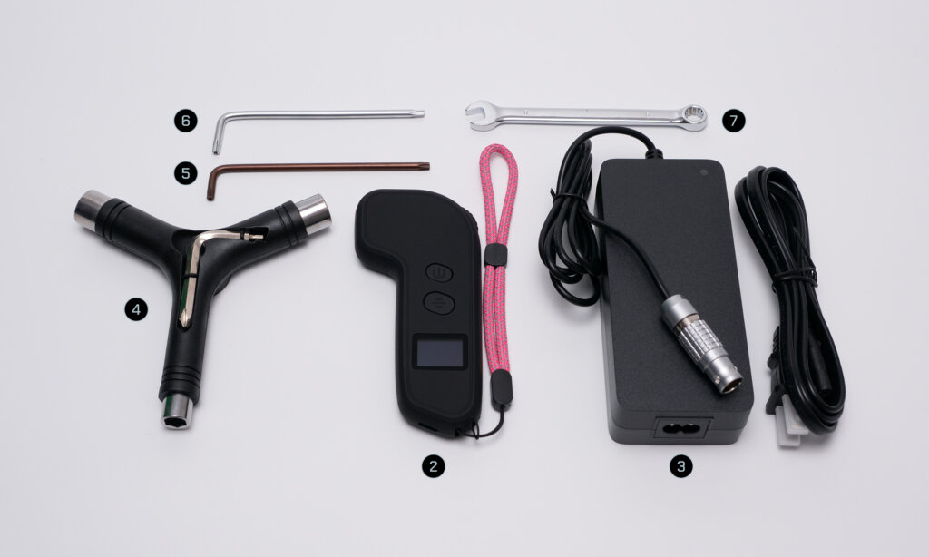
- Aero Electric Skateboard
- Provisional Remote Controller
- 165W Charger
- Skate Tool
- T20 Torx Key
- T25 Torx Key
- 8mm Wrench
Charging
Board
Plug the charger’s input cable into a power outlet. The charger’s power indicator should light up green.
Next, connect the output cable to the board. Within a few seconds, the indicator should turn red to show charging has started.
Once fully charged, the indicator returns to green.
Unplug the output cable from the board first, then unplug the input cable from the outlet.
Note: When using the 600W Fast Charger with the Aero Pro, plug the output cable into the board before connecting the input cable to the outlet. Charging will not begin if the input cable is plugged in first.
Remote
Plug a 5V USB cable into a power source. Then connect the USB-C end to the remote’s charge port. The remote’s display will show the charging status or indicate when charging is complete.
Note: The charging cable is not included as users likely already own one. Most USB-A to USB-C cables are 5V.
Caution
Only use the charger provided with the board or certified alternatives. Avoid charging in wet or humid conditions to reduce the risk of electric shock.
Turning On/Off
To turn on the board, press the Power Button on the front baseplate. To turn it off, press and hold the button for 1 second. (Turning off the board is generally unnecessary because of Standby Mode.)
To turn on the remote, press and hold its Power Button for 1 second. To turn it off, press and hold the button for 2 seconds.
When both the board and remote are on, they should connect automatically. If the display indicates that they are disconnected with a flashing X symbol, refer to the Pairing section in this manual to reconnect them.
The remote shuts off automatically after 5 minutes of inactivity.
Standby
When both the board and remote are on and connected, turning off the remote puts the board into Standby, a low power state similar to sleep mode on a computer. Turning the remote on again within 24 hours wakes the board from Standby.
While on Standby, the board shuts off automatically after 24 hours of inactivity.
Riding
If you’re new to skateboarding, we recommend watching these tutorials to familiarize yourself with longboarding basics:
On the remote, gently push the throttle wheel forward to accelerate. The farther forward you push, the more power is sent to the wheels.
Gently pull back on the throttle wheel to brake. The farther back you pull, the stronger the braking force.
Quick Tips
- Lean forward when accelerating.
- Lean back when braking.
Pushing
The board may be kick-pushed like a longboard in any of the following states.
- Board Turned On: While the drivetrain is engaged and the board is turned on, the belts and motors produce a small amount of resistance.
- Board Turned Off: While the drivetrain is engaged and the board is turned off, only the belts produce resistance.
- Belts Off: With the drivetrain disengaged, the board free-rolls like a traditional longboard.
To disengage or re-engage the drivetrain, see the section on Belt Replacement.
Additional Operations
Ride Modes
The provisional remote has four ride modes: L, E, S, and S+. Press the Mode Button to cycle through the four modes. The throttle wheel must be in the neutral position to change modes.
- L: Limp Mode intended for beginners.
- E: Economy Mode for experienced riders.
- S: Sport Mode for experienced riders.
- S+: S+upid Mode for situations that require more power. Use with caution.
Reverse
To change the ride direction to reverse, double-click the Mode Button. Double-click again to return to forward.
Before throttling up, check the direction indicator on the display to make sure the board will travel in the intended direction.
Cruise Control
To engage Cruise Control, ride at the desired speed and click the Power Button. Wait half a second before releasing the throttle wheel.
To disengage Cruise Control, do any of the following:
- Click the Power Button again
- Throttle up
- Brake
Although Cruise Control may be engaged at any speed, we strongly recommend engaging it at no higher than 10 mph (16 km/h).
Note: Use Cruise Control only on flat, familiar routes. Do not use it on hills, slopes, or irregular surfaces.
Additional Data
While not on the throttle and not in Cruise Control, click the Power Button to cycle through additional data shown at the bottom row of the interface.
- Trip Meter and Odometer (default)
- Voltage and Current
- ESC Temperature
- Motor RPMs
- Drive Type
- Drive Ratio
- Wheel Diameter
- Motor Pole Pairs
The bottom row data returns to default after 20 seconds.
Pairing & Setup Menu
To pair or re-pair the board and the remote, start with both devices turned off.
On the board, press and hold its Power Button for about 3 seconds. The button will blink rapidly to indicate that it is ready for pairing. (If the board was asleep rather than off, pressing and holding the Power Button will turn it off instead.)
On the remote, press and hold its Power Button for about 3 seconds. A REMOTE MODE menu will appear with the option of 2WD or 4WD. With 2WD highlighted, press the Power Button to continue.
The display will show “REMOTE PAIRING” with a radio signal animation to indicate that it is ready for pairing. If both devices are in pairing mode, pairing will occur immediately, and the Setup Menu will appear.
Use the Throttle Wheel to change a selection. Use the Power Button to confirm a selection. The following are the default settings.
SPEED UNIT: MPH
MOTOR TYPE: BELT/GEAR
WHEEL DIAM: 80
DRIVE RATIO: 2.6
MOTOR POLE PAIRS: 7
BRAKE LEVEL: 100
The settings for SPEED UNIT and BRAKE LEVEL may be changed if desired.
All Aero models use belt drive so keep the MOTOR TYPE selection at BELT/GEAR.
Change the WHEEL DIAM if the installed wheels are not 80 millimeters in diameter.
Change the DRIVE RATIO if the wheel pulleys have been changed to a different size. To calculate the ratio, divide the tooth count of the wheel pulley with the tooth count of the drive gear, and then round to the nearest tenths.
Keep the MOTOR POLE PAIRS at 7.
The BRAKE LEVEL setting may be changed if you feel the brakes are too strong or too weak.
Advanced Parameters
The Advanced Parameters screen is accessed by clicking the Mode Button 8 times in succession while both the remote and board are on.
Menus 1 through 9
1. SPEED MODE
Keep this setting unchanged.
2. MOTOR RUN MODE
Keep this setting on HYBRID.
3. MAX SPEED
Lower the maximum speed if desired. For your safety, raising the maximum speed above default is not recommended.
4. BATT OUT MAX
Keep this value at 100%.
5. BATT CELLS
Keep this setting at 14S.
6. BATT TYPE
Keep this setting at 21700.
7. DRIVER FREQ
Keep this value at 0.
8. MAX BRAKE
Adjust the maximum braking force if desired.
9. MOTOR RUN DIR
Keep this setting at its default value. Change if the wheels are spinning the wrong way.
Note: The MAX SPEED parameter is currently capped at 31 mph (50 km/h). While it is possible to achieve a higher top speed through other means, the displayed speed will show a lower value. We do not recommend attempting this as it may affect performance and safety.
Menus 10 through 25
Menus 10 through 25 are for setting the parameters of each ride mode (L, E, S, S+).
MODE REF
This sets the top speed of the ride mode as a percentage of the value set in the MAX SPEED menu. L MODE REF may not exceed 50%, and E MODE REF may not exceed 60%.
MODE CUR
This sets the maximum power of the ride mode. L MODE CUR may not exceed 50%, and E MODE CUR may not exceed 60%.
SPEEDUP LINE
This sets the acceleration curve of the ride mode. A lower percentage reaches maximum power more slowly, and a higher percentage more quickly.
BRAKE LINE
This sets the braking curve of the ride mode. A lower percentage reaches maximum braking force more slowly, and a higher percentage more quickly.
Reset Parameters
26. RESTORE PARA
This resets all parameters to factory default.
Note: The Aero Pro ships with custom performance parameters that differ from the factory defaults. They are as follows.
- MAX SPEED: 27 MPH / 43 KPH
- L MODE REF: 40
- L MODE CUR: 15
- L SPEEDUP LINE: 10
- L BRAKE LINE: 40
- E MODE REF: 60
- E MODE CUR: 40
- E SPEEDUP LINE: 10
- E BRAKE LINE: 50
- S MODE REF: 100
- S MODE CUR: 60
- S SPEEDUP LINE: 10
- S BRAKE LINE: 60
- S+ MODE REF: 100
- S+ MODE CUR: 100
- S+ SPEEDUP LINE: 10
- S+ BRAKE LINE: 60
- MOTOR RUN DIR: Change if the wheels spin in the wrong direction.
Maintenance
Routine
- Check that all fasteners are secure.
- Wiggle each truck to check for slop and loose fasteners.
- Shake each wheel along its axle to make sure it’s secure.
- Spin each wheel to watch and listen for damaged bearings.
- Inspect the drivetrain for stuck debris and excessive wear.
- Inspect the wheels for uneven wear. Rotate the position of the wheels if necessary.
Cleaning
- Do not pressure wash or submerge the board!
- Do not pour or spray water onto the board!
- Wipe off dirt and dust with a damp cloth. Then dry with a drying towel.
- For the grip tape, use a soft-bristle brush or grip tape cleaner.
- Clean bearings with isopropyl alcohol or replace them with new ones.
Lubrication
- Lubricate bearings with skate bearing lube every 300 miles or 500 kilometers. Alternatively, replace old or damaged bearings with new ones when necessary.
- If a truck squeaks loudly when turning, lubricate its pivot pin, kingpin, and bushing seats with a small amount of silicone-based lube. Don’t use oil-based lube.
- Avoid over-lubrication as that can attract dirt.
Storage and Battery Care
- Store the board indoor between 5 and 25 ºC (41 and 77 ºF).
- Avoid storing under constant direct sunlight.
- Avoid storing in humid conditions.
- Do not store in a hot car.
- For long-term storage, charge or discharge the battery to around 50%.
- Fully discharge and recharge the battery once every 3 months, including during long-term storage.
- Do not store at temperatures below -20 ºC (-4 ºF).
- Do not leave the battery at either 0% or 100% charge for more than a week as doing so may accelerate degradation.
- Avoid leaving the charger plugged in for more than 2 hours after the battery is fully charged.
- Partial charges are totally fine. Charging from 20% to 80% puts less strain on the battery than from 0% to 100%.
- Use the charger that came with the board.
- Plug the charger into the wall first, then into the board.
- Do not expose the board to rapid temperature changes that can cause condensation.
Belt Replacement
In Aero’s default configuration, replacing a belt takes as little as 15 seconds and no tools are required. Follow these same steps for drivetrain disengagement and re-engagement.
Removing a Belt
- Gently pry the belt off of the drive gear using your fingers. Spinning the wheel back and forth slightly at the same time may help.
- With the belt disconnected from the gears, slip it over the wheel and away from the drivetrain.
If aftermarket wheels are installed, removing the wheel may be necessary before step 1.
If the drivetrain is not in its default configuration, loosening the belt tension may be necessary before step 1.
Installing a Belt
- Slip the replacement belt over the wheel and onto the wheel pulley.
- With one hand holding the belt in place on the driven gear, use the other hand to partially position the belt’s smooth side over the idler pulley.
- Gently pull the belt and slide it onto the drive gear. Spinning the wheel slightly may help.
If using a larger wheel, it may need to remain off before step 1 and be installed after the belt is installed.
If the drivetrain is not in its default configuration, loosening the belt tension and leaving the wheel off may be necessary before step 1.
Belt and Pulley Combinations
Each motor mount plate on the E.P.I.C. Drivetrain has three preset positions for the idler pulley and two for the motor. These presets remove the need for belt tension adjustments that conventional belt drive systems require.
Note: The bolt securing the right-side idler pulley has reverse threads. Turn it clockwise to loosen, counterclockwise to tighten.
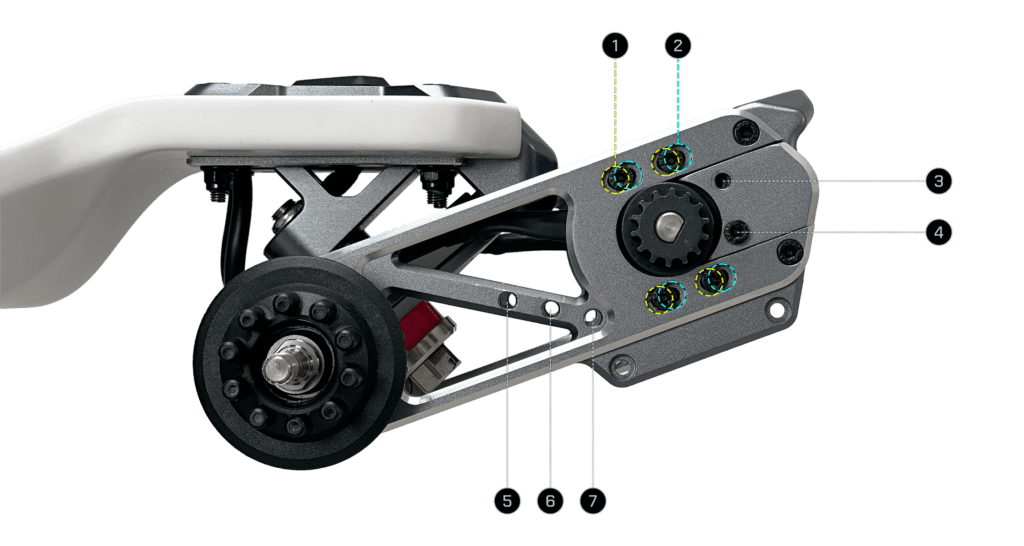
- Motor Frontmost Position
- Motor Rearmost Position
- Motor Upper Preset Position
- Motor Lower Preset Position
- Idler Front Position
- Idler Middle Position
- Idler Rear Position
Recommended Setups
32T Pulleys
HTD 340-5M-15
Motor Upper Preset Position
Idler Middle Position
36T Pulleys
HTD 350-5M-15
Motor Lower Preset Position
Idler Middle Position
40T Pulleys
HTD 360-5M-15
Motor Frontmost Position
Idler Middle Position
45T Pulleys
HTD 375-5M-15
Motor Lower Preset Position
Idler Middle Position
Compatible Setups for 36T Pulleys
Compatible Setups for 40T Pulleys
Belt Tension Adjustment
Belt tension adjustment is generally not required on the Aero Pro but it is available as an option.
- Remove the Motor Position Preset screw using a T20 Torx key.
- Loosen all four motor screws using a T20 Torx key.
- Adjust the motor position until the belt tension reaches the desired level.
- Tighten one upper screw and one lower screw to keep the motor in place. Check that the belt tension remains at the desired level.
- Apply threadlocker to each of the loose screws and tighten them.
- Apply threadlocker to the remaining screws and tighten them as well.
- Check again that the belt tension is at the desired level. If necessary, loosen the screws to adjust the motor’s position, and then tighten the screws once the desired belt tension is achieved.
- Allow time for the threadlocker to cure before riding.
Customer Support
Contact us for assistance.
Compliance
This device complies with part 15 of the FCC Rules. Operation is subject to the following two conditions:
(1) This device may not cause harmful interference, and
(2) this device must accept any interference received, including interference that may cause undesired operation.